DXF import was added to D2nc as a way of getting more complex shapes which cannot be described with SDL, into D2nc. I like to refer to it as shape extraction where a shape is extracted from the DXF file. Once you have extracted a shape, the steps required to generate g-code, that is the setting of constraints and defining tool paths, are the same as if the shape had been described with SDL.
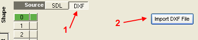
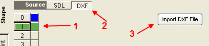
To import a DXF file first select the DXF shape source and then click the Import button. In the open file dialog, browse to the directory containing your DXF file, select the file you wish to import and then click the Open button. You will find a sample DXF file in C:\D2nc directory with the name D2ncsample.dxf which I will use in this tutorial.

The filter panel is the first of two panels used during shape extraction. The Elements, defaulted to Lines and Arcs, control which elements in the DXF are extracted into the shape. The Layers determine from which layer those elements are extracted. The choices are either the default All layers or any other named layer in the DXF file.
Note!
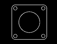
The idea is to import just the elements needed for one machining operation into one shape. Change the filter to All elements and All Layers to reveal the full contents of the sample DXF file. This file contains a flange requiring three operations. One, drill the four corner holes. Two, cut the center hole offset to the inside and three, cut out the part from the stock by offsetting to the outside. The three operations we've now determined will require importing the DXF three times and each time extracting different elements into a new shape.
To create our first shape to drill the four corner holes, change the filter to Circles as Points and click the Next button. In D2nc, only points can be used for defining a drilling operation.
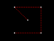

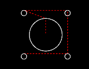
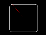
The five circles in the DXF file have been converted to points and imported. The points are indicated by the white dots in the display area and the read dashed lines the tool movement. All other elements in the DXF file have been ignored.
We have a point in the center of the shape originating from the large center circle. It too was converted to a point but as we don't want to drill there, we need to remove it. Place the mouse pointer over the white dot and click to select it. Once selected it will turn red.
NOTE!
Some older graphic card that do not support OpenGL V2 will not be able to click select chains and elements with the mouse. An alternate method is to use the left and right arrow keys to cycle through chains or elements (depend on the selected option). One one chain or element can be selected at a time. Use the DEL key to remove the selected item.
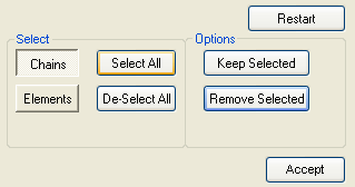
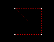
Click the Remove Selected button to eliminate the selected elements. Click the Accept button to lock in the shape.
Now that we have shape 0 locked in, select shape 1 then the DXF source and then Import. Select the same DXF to import and click Open. Set the filter to Circles and click Next.
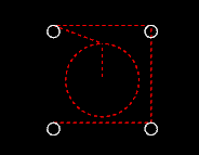

The five circles in the DXF file have been imported. Click on the large center circle to select it. Now click the Keep Selected button which will remove all elements that are not selected leaving us with the shape for the inside offset. Click the Accept button to lock in the shape.
The last shape we need is that of the outside contour. We have shape 0 and 1 locked in so select shape 2 then the DXF source and then Import. Select the same DXF to import and click Open. Set the filter to Lines and Arcs and click Next.
This shape needs no adjustment so we just click Accept to lock it in.
Congratulations, you have successfully extracted the three shapes from the DXF file which are required for the three machining operations needed on this particular part. You may now proceed to set the constraints, define the tool paths and then generate g-code.


