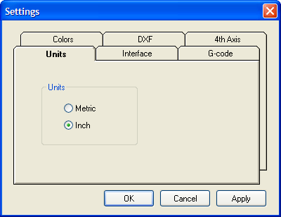
Select the units you will working in.
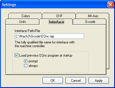
The file name that the g-code is saved to when you click the "Generate G-Code to File" button
Set the option of loading the previous program you were working on at startup. Additionally you can be prompted to make a Yes or No decision to load the previous program or just load it every time.
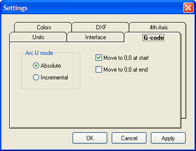
This option sets how the I and J components of G02 and G03 are generated. Either as an absolute coordinate or incremental to the X and Y coordinate of the G02 or G03 move. This setting must match the same setting in Mach3. See installation for further information. If these settings are different all arcs will look strange and may manifest itself by showing arcs going in the wrong direction or as mirror images of what they should be. Be aware that some of the Mach3 built-in wizards may change the setting in Mach3 and cause it to be out of sync with the setting in D2nc.
Move to 0,0 at start and at end will include these moves in the generated g-code if checked.
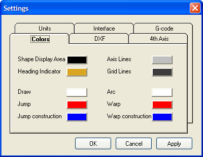
You may customize the colors by clicking on a swatch and selecting a new color from the picker presented.

When importing DXF files, any element endpoint's within proximity to each other by the defined tolerance, are considered joined together.
A CAD program launch button can be enabled allowing for easier creation or modification of DXF files. Change the name of the button and the path to the CAD program executable for your environment.

Specify the location and rotational direction of the 4th axis. For each setting the narrative will change describing the setup.
The arc conversion converts all arc's to line segments the smaller of a max angle or a segment length. For a particular radius, an angle of 90 degrees will be generated with either 45 line segments (spanning 2 degrees each) or as many .010 segments fit the curve, whichever is greater, given the default values above.


