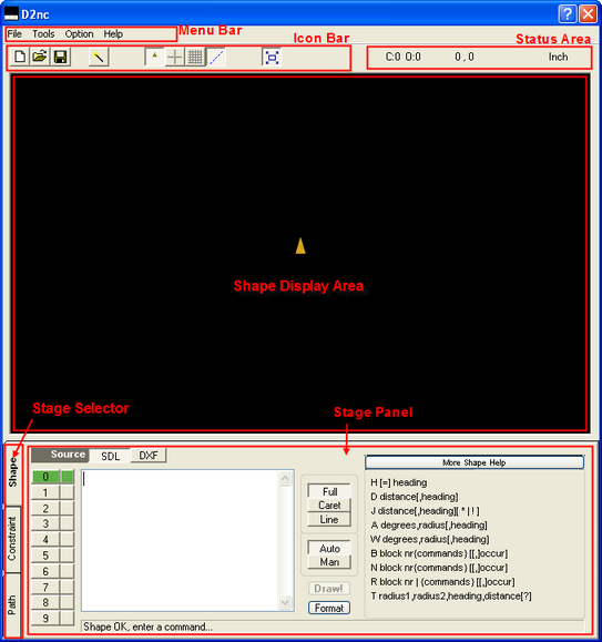
Menu Bar
Program Menu
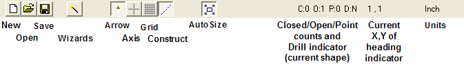
Icon Bar
New
Open
Save
Wizards loads the SDL wizard selection screen.
Arrow shows/hides the yellow arrow heading indicator.
Axis shows/hides the X and Y axis and the zero intersect.
Grid shows/hides the display grid lines.
Construct shows/hides the red and blue jump and construction lines.
Autosize Auto/Manual resize of the shape in the display area.
Status Area
C: shows the number of closed chains in the current shape.
O: shows the number of open chains in the current shape.
P: shows the number of points in the current shape.
(NOTE! : The first 3 counts are important as only a single closed shape with no open shapes and points can be offset using G41/G42. That is; offset buttons will only be enabled if the status is C:1 O:0 P:0)
D: indicator Y/N shows if the shape can be used for drilling. The drill operation buttons are only enabled if this is a Y.
X,Y shows the current location of the heading indicator in the shape display area.
Units shows the current working units. Inch or Metric. This is changeable in the settings menu.
Shape Display Area
The black area is where shapes are displayed. This is an output only area. Shapes are defined using the Shape Description Language while in the Shape mode.
Using the Mouse.
Right drag - Hold the right mouse button down to drag the shape around.
Shift left drag or scroll wheel - Hold the shift key and left mouse button down and move the mouse up to zoom in or down to zoom out. This can also be done by clicking on the display area and rolling the mouse scroll wheel.
Stage Selector
There are three program stages which need to be followed to generate g-code. The stages are:
Describe Shapes
Set Constraints
Define Paths
Stage Panel
Activities for the current stage are carried out in this area. See Stage Selector above for descriptions of the stages.


